- 您现在的位置:买卖IC网 > Sheet目录341 > MAX8930EWJ+T (Maxim Integrated)IC LED DRVR WT/RGB BCKLGT 49WLP
�� �
�
 �
�MAX8930�
�WLED� Charge� Pump,� RGB,� OLED� Boost,�
�LDOs� with� ALC� and� CAI�
�SDA�
�t� BUF�
�t� LOW�
�t� SU� ,DAT�
�t� HD,DAT�
�t� SU,STA�
�t� HD,STA�
�t� SU,STO�
�SCL�
�t� HD,STA�
�t� R�
�t� HIGH�
�t� F�
�START�
�CONDITION�
�REPEATED� START�
�CONDITION�
�STOP�
�CONDITION�
�START�
�CONDITION�
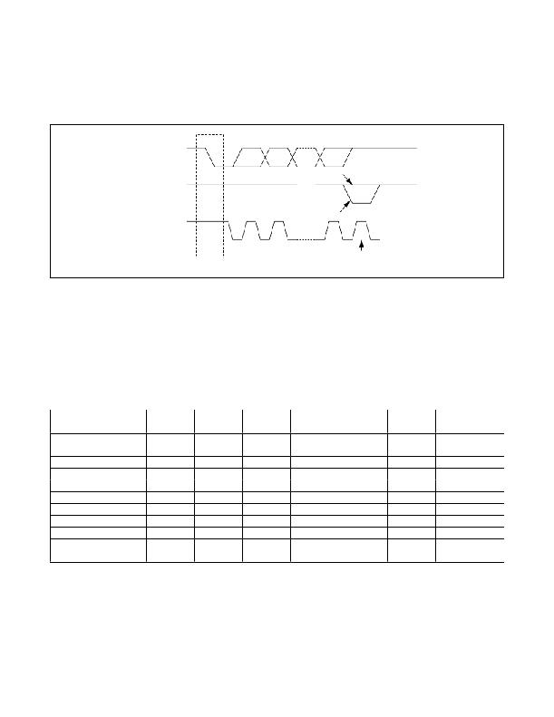
�Figure� 11.� START� and� STOP� Conditions�
�SDA�
�SCLK�
�MASTER�
�TRANSMITTER/�
�RECEIVER�
�Figure� 12.� I� 2� C� Master� and� Slave� Configuration�
�SLAVE�
�RECEIVER�
�SLAVE�
�TRANSMITTER/�
�RECEIVER�
�I� 2� C� Bit� Transfer�
�One� data� bit� is� transferred� for� each� clock� pulse.� The� data�
�on� SDA� must� remain� stable� during� the� high� portion� of�
�the� clock� pulse� as� changes� in� data� during� this� time� are�
�interpreted� as� a� control� signal.�
�I� 2� C� START� and� STOP� Conditions�
�Both� SDA� and� SCL� remain� high� when� the� bus� is� not�
�busy.� A� high-to-low� transition� of� SDA,� while� SCL� is� high� is�
�defined� as� the� START� (S)� condition.� A� low-to-high� transi-�
�tion� of� the� data� line� while� SCL� is� high� is� defined� as� the�
�STOP� (P)� condition.�
�Maxim� Integrated�
�I� 2� C� System� Configuration�
�A� device� on� the� I� 2� C� bus� that� generates� a� message� is�
�called� a� transmitter� and� a� device� that� receives� the� mes-�
�sage� is� a� receiver.� The� device� that� controls� the� message�
�is� the� master� and� the� devices� that� are� controlled� by� the�
�master� are� called� slaves.�
�I� 2� C� Acknowledge�
�The� number� of� data� bytes� between� the� START� and� STOP�
�conditions� for� the� transmitter� and� receiver� are� unlimited.�
�Each� 8-bit� byte� is� followed� by� an� acknowledge� bit.� The�
�acknowledge� bit� is� a� high-level� signal� put� on� DATA� by�
�the� transmitter� during� which� time� the� master� generates� an�
�extra� acknowledge� related� clock� pulse.� A� slave� receiver�
�that� is� addressed� must� generate� an� acknowledge� after�
�each� byte� it� receives.� Also,� a� master� receiver� must� gen-�
�erate� an� acknowledge� after� each� byte� it� receives� that�
�has� been� clocked� out� of� the� slave� transmitter.�
�33�
�发布紧急采购,3分钟左右您将得到回复。
相关PDF资料
MAXQ2000-KIT
EVAL KIT FOR MAXQ2000
MAXQ610-KIT#
EVALUATION KIT FOR MAXQ610
MB2146-401-01A
KIT STARTER F2MC-8FX 3V
MB2146-401-03A
KIT STARTER F2MC-8FX 5V
MB2146-410A-01-E
KIT STARTER MB95200/210H SERIES
MB85R1001ANC-GE1
IC FRAM 1MBIT 150NS 48TSOP
MB85R1002ANC-GE1
IC FRAM 1MBIT 150NS 48TSOP
MB85R256FPFCN-G-BNDE1
IC FRAM 256KBIT 150NS 28TSOP
相关代理商/技术参数
MAX8931EVKIT+
制造商:Maxim Integrated Products 功能描述:5V RS232 TRANSCEIVER - Boxed Product (Development Kits)
MAX8932EVKIT+
功能描述:电池管理 RoHS:否 制造商:Texas Instruments 电池类型:Li-Ion 输出电压:5 V 输出电流:4.5 A 工作电源电压:3.9 V to 17 V 最大工作温度:+ 85 C 最小工作温度:- 40 C 封装 / 箱体:VQFN-24 封装:Reel
MAX8932EWT120+T
功能描述:电池管理 RoHS:否 制造商:Texas Instruments 电池类型:Li-Ion 输出电压:5 V 输出电流:4.5 A 工作电源电压:3.9 V to 17 V 最大工作温度:+ 85 C 最小工作温度:- 40 C 封装 / 箱体:VQFN-24 封装:Reel
MAX8934AETI+
功能描述:电池管理 Dual Linear Charger Smart Power Selector RoHS:否 制造商:Texas Instruments 电池类型:Li-Ion 输出电压:5 V 输出电流:4.5 A 工作电源电压:3.9 V to 17 V 最大工作温度:+ 85 C 最小工作温度:- 40 C 封装 / 箱体:VQFN-24 封装:Reel
MAX8934AETI+T
功能描述:电池管理 Dual Linear Charger Smart Power Selector RoHS:否 制造商:Texas Instruments 电池类型:Li-Ion 输出电压:5 V 输出电流:4.5 A 工作电源电压:3.9 V to 17 V 最大工作温度:+ 85 C 最小工作温度:- 40 C 封装 / 箱体:VQFN-24 封装:Reel
MAX8934BETI+
功能描述:电池管理 Dual Linear Charger Smart Power Selector RoHS:否 制造商:Texas Instruments 电池类型:Li-Ion 输出电压:5 V 输出电流:4.5 A 工作电源电压:3.9 V to 17 V 最大工作温度:+ 85 C 最小工作温度:- 40 C 封装 / 箱体:VQFN-24 封装:Reel
MAX8934BETI+
制造商:Maxim Integrated Products 功能描述:IC BATTERY CHARGER DUAL 28TQFN
MAX8934BETI+T
功能描述:电池管理 Dual Linear Charger Smart Power Selector RoHS:否 制造商:Texas Instruments 电池类型:Li-Ion 输出电压:5 V 输出电流:4.5 A 工作电源电压:3.9 V to 17 V 最大工作温度:+ 85 C 最小工作温度:- 40 C 封装 / 箱体:VQFN-24 封装:Reel